What is a Gas Valve Train?
A gas valve train is an assembly of valves, regulators, pressure switches, and monitoring devices that controls and shuts off fuel flow to an industrial burner. It helps ensure proper fuel delivery, verifies safe operating conditions, and stops gas flow automatically if a fault is detected to reduce fire and explosion risk.
Gas Train Diagram
Below is a labeled diagram outlining the key components of a typical industrial gas valve train.
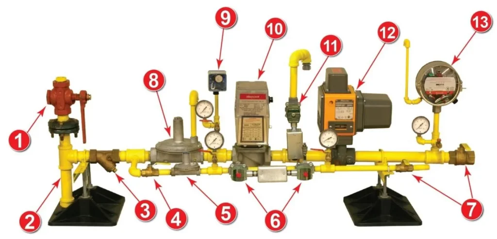
Gas Train Components
- Main Gas Shut-Off Valve
- Sediment Trap
- Strainer
- Pilot Gas Manual Valve
- Pilot Regulator
- Pilot Solenoid Valves
- Downstream Shut Off Valve
- Main Gas Regulator
- Low Gas Pressure Switch
- Safety Shut-Off Valve
- Double Block & Bleed Vent Valve
- Blocking Valve
- High Gas Pressure Switch
How Does a Valve Train Work?
A gas valve train controls, monitors, and safely shuts off fuel to a burner using valves, regulators, pressure switches, and other safety devices. The gas train diagram above shows where these components sit in the fuel line and the order they operate. The light off sequence below explains how the burner management system checks those same valve train devices, completes purge, proves flame, and then opens the safety shutoff valves to allow safe ignition and steady operation.
Light Off Sequence and Valve Train Operation
On a call for heat, the Burner Management System (BMS) checks the Low and High gas pressure switches, the proof of closure switch, and initiates the purge cycle. The purge fan comes on. The purge timing starts when the airflow switch senses that sufficient airflow is being provided. When the purge timing is complete, the BMS verifies that the firing rate valve is in the low fire start position, the igniter sparks, and the pilot solenoid valves open. The BMS timer allows only 10 seconds for the flame detector to prove the pilot flame. Once a pilot is verified, the Safety Shut Off Valve and the Blocking Valve open and the Vent Valve closes. The BMS timer initiates a 10-second period during which the pilot valve and igniter are de-energized and only the main flame must be detected. The BMS then releases control of the burner to the firing rate controller and assumes a monitoring role.
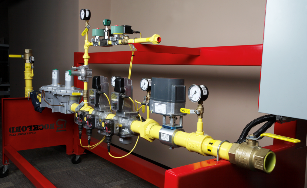
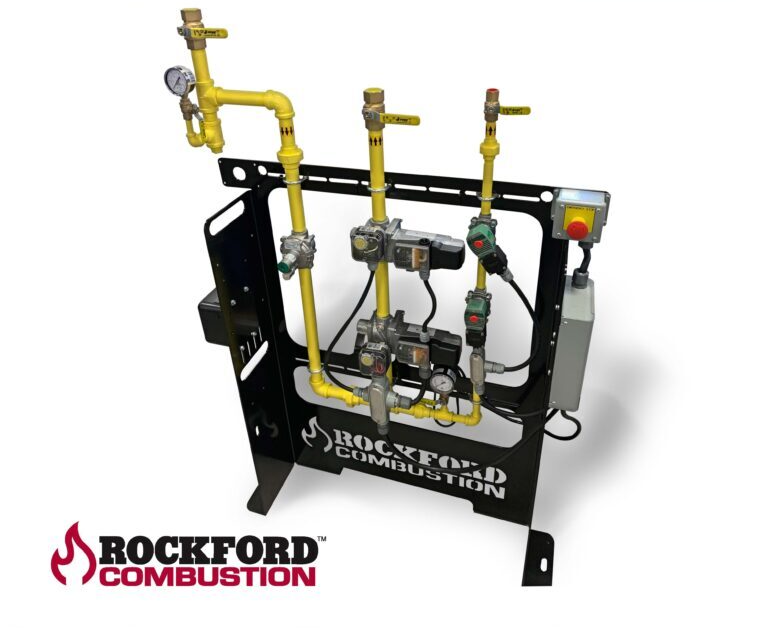
Types of Valve Trains
Examples of different standard valve train systems offered by Rockford Systems.
Company Man o’ War 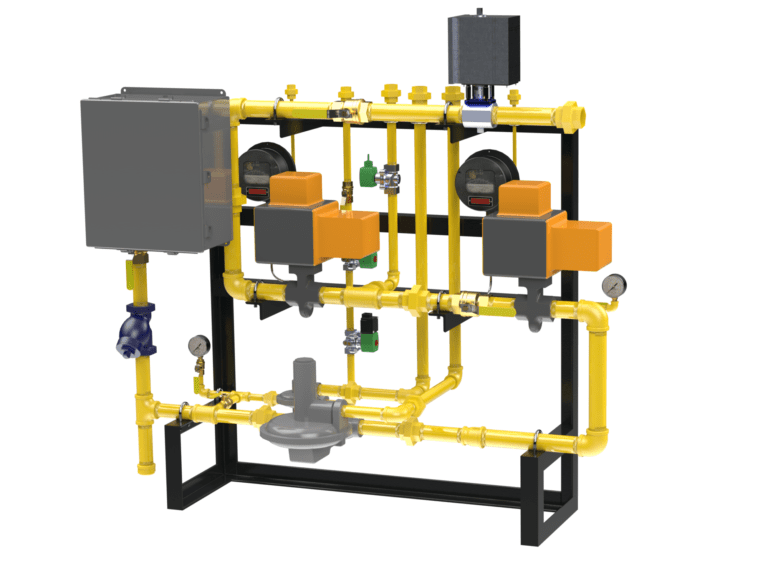
Vented Valve Train 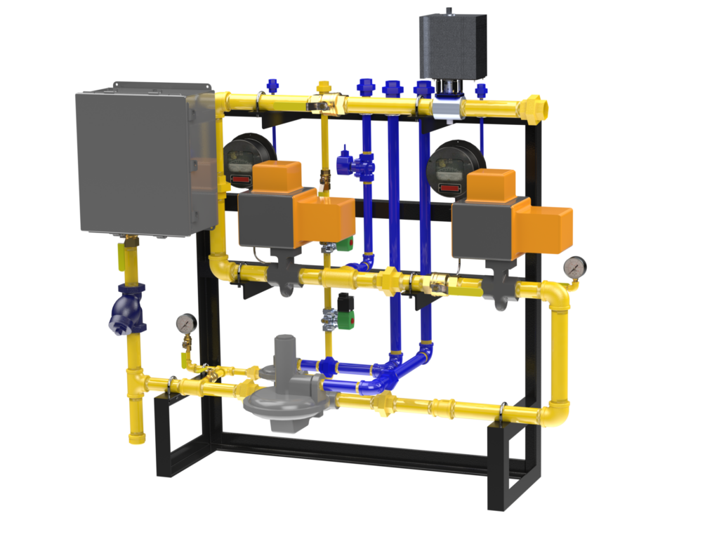
Targeted Components 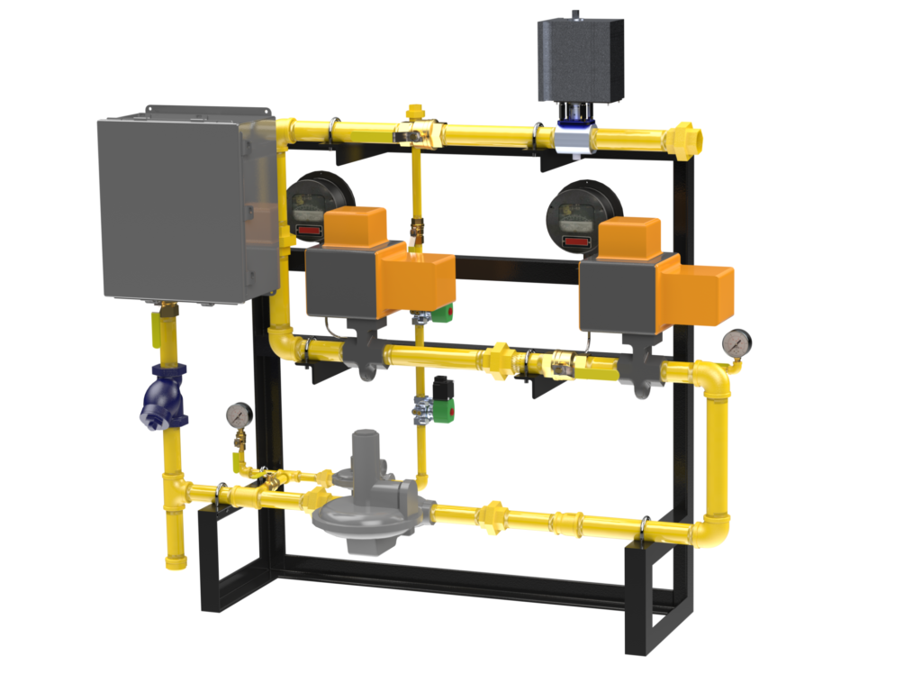
Removed Components 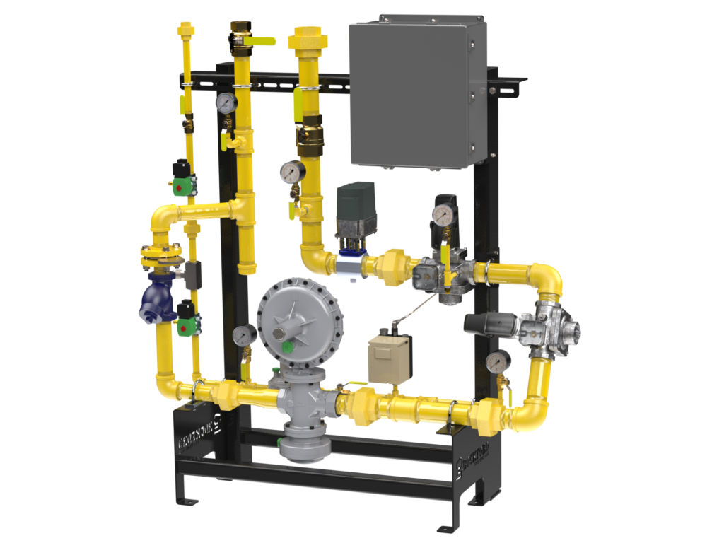
Ventless Valve Train
Optimizing Valve Train Safety and Performance
Rockford Combustion offers tailored fuel trains and combustion safety solutions to improve combustion system safety, efficiency, and compliance. From fuel-train design and installation to ongoing support and risk assessments, our comprehensive approach ensures your valve train systems operate at peak performance.